Crosby Eliminator
WARNING |
- Failure to read, understand, and follow these instructions may cause death or serious injury.
- Read and understand these instructions before using the Crosby ELIMINATOR®.
- Incorrectly rigging or terminating exerts additional force or loading, which the Crosby ELIMINATOR® is not designed to accommodate.
|
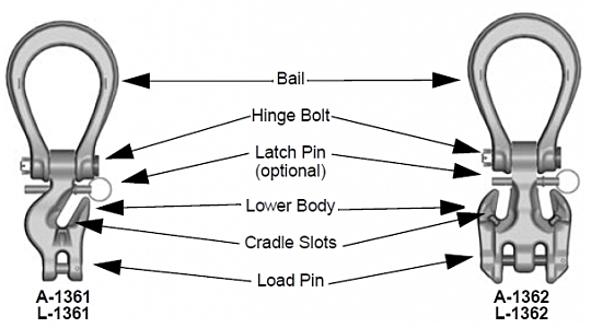
Crosby ELIMINATOR® Definitions
The Crosby ELIMINATOR® consists of a bail, hinge pin, latch pin, and lower body with cradle slot/slots.
The Crosby ELIMINATOR®incorporates markings forged into the product which address a QUIC-CHECK® feature:
Deformation Indicators - Two strategically placed marks on each leg of the bail, which allows for a QUIC-CHECK® measurement to determine if the bail opening has changed, thus indicating abuse or overload. To check, use a measuring device (i.e. tape measure) to measure the distance between the marks. The marks should align to either an inch or half-inch increment on the measuring device. If the measurement does not meet criteria, the Crosby ELIMINATOR® bail should be inspected further for possible damage.
Important Safety Information Read and Follow
- A visual periodic inspection for cracks, nicks wear, gouges and deformation as part of a comprehensive documented inspection program, should be conducted by trained personnel in compliance with ANSI B30.9.
- Remove from service any Crosby ELIMINATOR® components with a crack, nick, or gouge. The bail and body of a Crosby ELIMINATOR® with nick or gouge shall be repaired by a qualified person. The qualified person shall repair by grinding longitudinally following the contour of the forging, provided that the reduced dimension is within the limits shown in (Fig. A). Never use a Crosby ELIMINATOR®that is worn beyond the limits shown in Fig. A.
 |
- Never repair, alter, rework, or reshape a Crosby ELIMINATOR® by welding, heating, burning, or bending.
- Crosby ELIMINATOR®combination master link and chain shortener shall not be used in a manner other than that for which it is intended.
- The sling may be shortened by use of the cradle slot/slots (see Fig. C).
- In shortening applications, the Crosby ELIMINATOR® can be used without any reduction to the Working Load Limit.
- Never terminate (i.e. place a load bearing chain sling hook), or reeve load bearing chain through Crosby ELIMINATOR® bail (see Fig. B).
- Never exceed the rated capacity shown on sling's identification tag.
- Attach lifting device to ensure free fit of Crosby ELIMINATOR® bail (see Fig. D). Never allow lifting device to apply forces on side of bail (see Fig. E), as this condition will damage and reduce the capacity of the Crosby ELIMINATOR®.
- The Crosby ELIMINATOR® is intended for tension or pull. Side loading must be avoided, as it exerts additional force or loading which the product is not designed to accommodate (see Fig. F).
- Never use a Crosby ELIMINATOR®where the bail shows signs of deformation or overloading (see Table 1).
- Read and understand the other sections of the ALLOY STEEL CHAIN SLINGS Warning, Selection, Use & Maintenance Information.
TABLE 1 |
Crosby ELIMINATOR® Bail Dimensions |
Chain
Size |
Frame
I.D.
Code |
Inside Length (in.) |
Inside
Width
(in.) |
Jaw
Width
(in.) |
QUIC-CHECK®
Dim
(in.) |
(in.) |
(mm) |
1/4 - 5/16 |
7 - 8 |
2 |
3.88 |
3.00 |
.94 |
3.50 |
3/8 |
10 |
3 |
4.81 |
3.50 |
1.13 |
4.00 |
1/2 |
13 |
4 |
6.00 |
4.13 |
1.31 |
5.00 |
5/8 |
16 |
5 |
6.88 |
4.75 |
1.63 |
6.00 |
- A Crosby ELIMINATOR® under load shall be allowed to self-align itself about the hinge pin.
- The use of a latch may be mandatory by regulations or safety codes; e.g. OSHA, MSHA, ANSI/ASME B30.10 and B30.9.
- If Crosby latch pin is present, it should fit and function properly, and show no signs of distortion or bending.
- Always make sure the chain is seated in the cradle slot, and the cradle supports the load. The latch pin must never support the load.
- Latch pins are not intended to be an anti-fouling device.
- Use only genuine Crosby repair and latch pins parts.
A-1361 Single Leg Crosby ELIMINATOR®
- The A-1361 single leg Crosby ELIMINATOR® is designed to support a single leg vertical load. The cradle slot may be used to make a loop in the leg (see Fig. G). However, the Working Load Limit is still limited to the single leg values shown in Table 4 (Grade 100) and Table 5 (Grade 80). (See page 230 for tables.)
- To produce a single basket hitch and achieve the full Working Load Limit, use only one length of chain with both ends terminated into the load pins of two A-1361 single leg Crosby ELIMINATOR® fittings (see Fig. H). Basket may be shortened with cradle slot.
- Never exceed the single leg Working Load Limit shown in Table 4 (Grade 100) and Table 5 (Grade 80) for an individual A-1361 Crosby ELIMINATOR® fitting.
A-1362 Double Leg
Crosby ELIMINATOR®
- The A-1362 double leg Crosby ELIMINATOR® is designed to support symmetrically loaded double leg slings at 60, 45, and 30 degree horizontal angles. The cradle slots may be used to make loops in the legs (see Fig. J). However, the Working Load Limit is limited to the double leg values shown in Table 4 (Grade 100) and Table 5 (Grade 80).
- To produce a single basket hitch, and achieve the full Working Load Limit, use only one length of chain with both ends terminated into the load pin (see Fig. K). Basket may be shortened with the cradle slot or slots.
- To produce a double basket hitch and achieve the full Working Load Limit, two A-1362 double leg Crosby ELIMINATOR® fittings must be used, with both being terminated at their load pin (see Fig. L).
- Never exceed the double leg / single basket Working Load Limit on an individual A-1362 Crosby ELIMINATOR® fitting.
|